


Ec buying
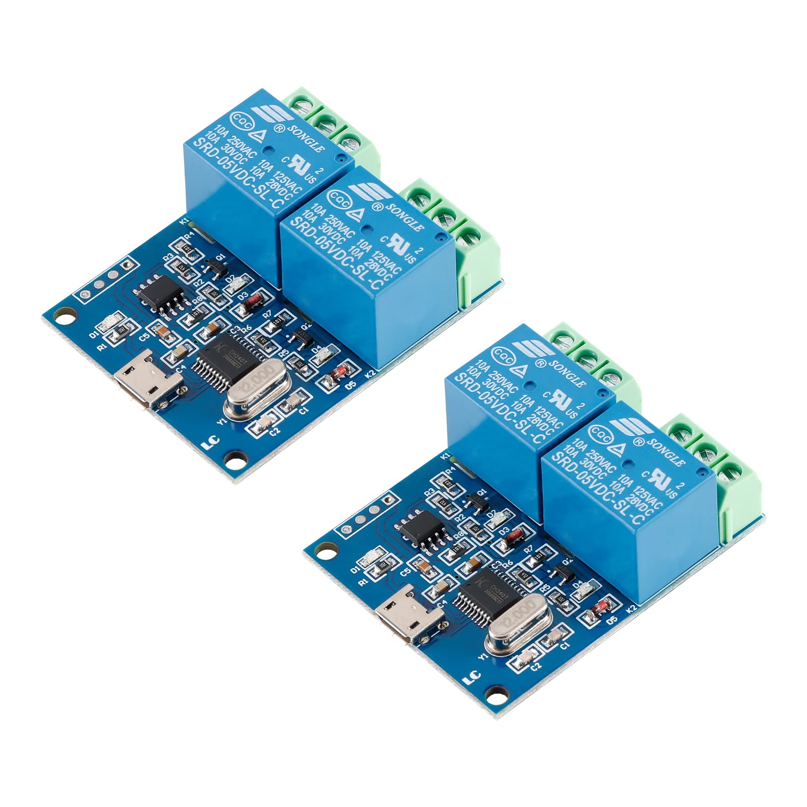
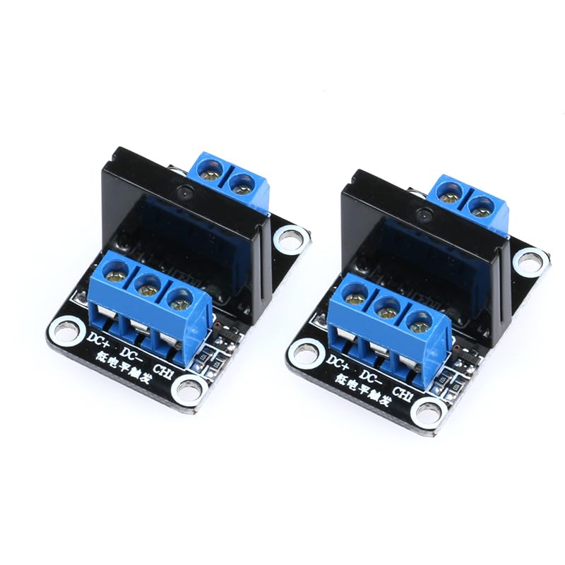
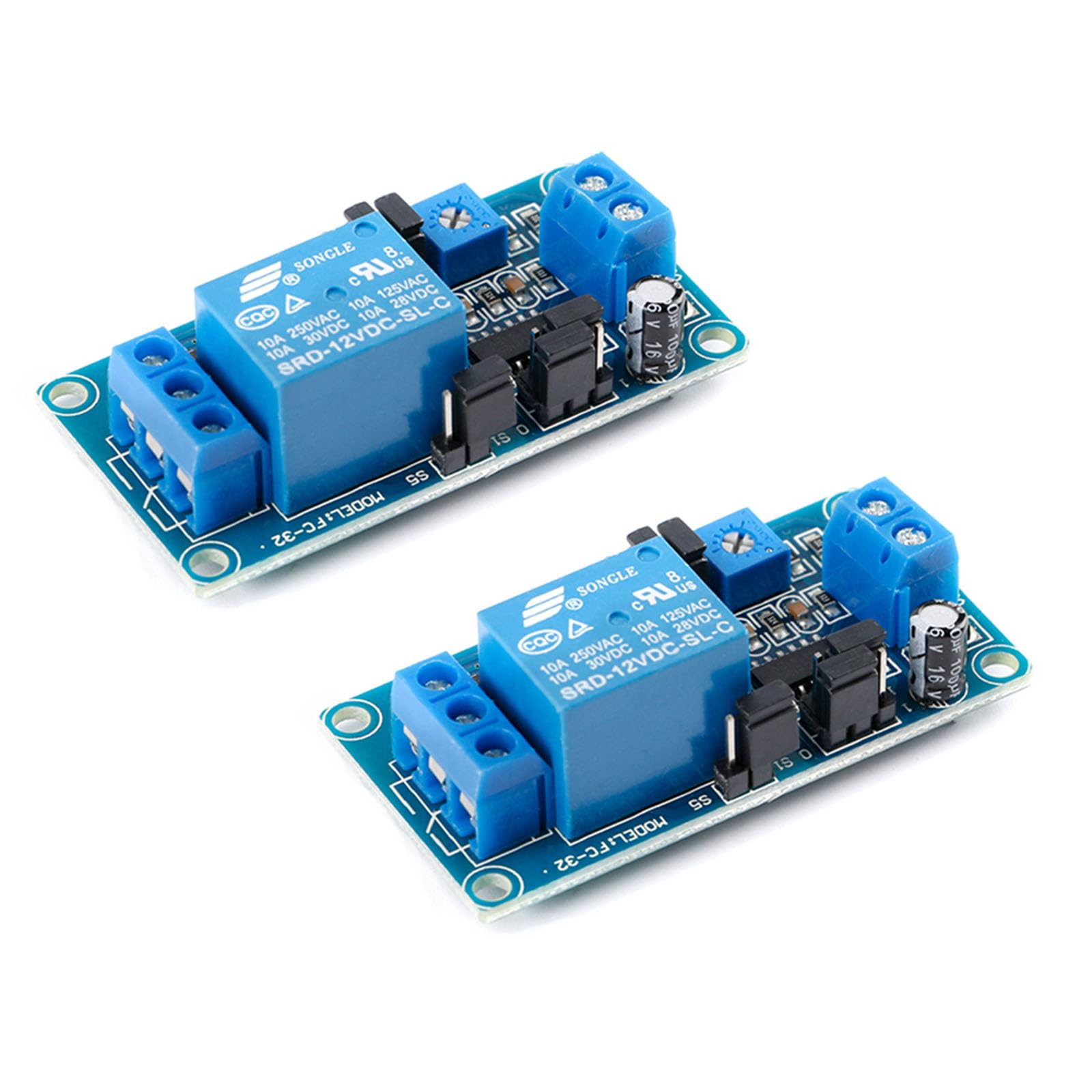
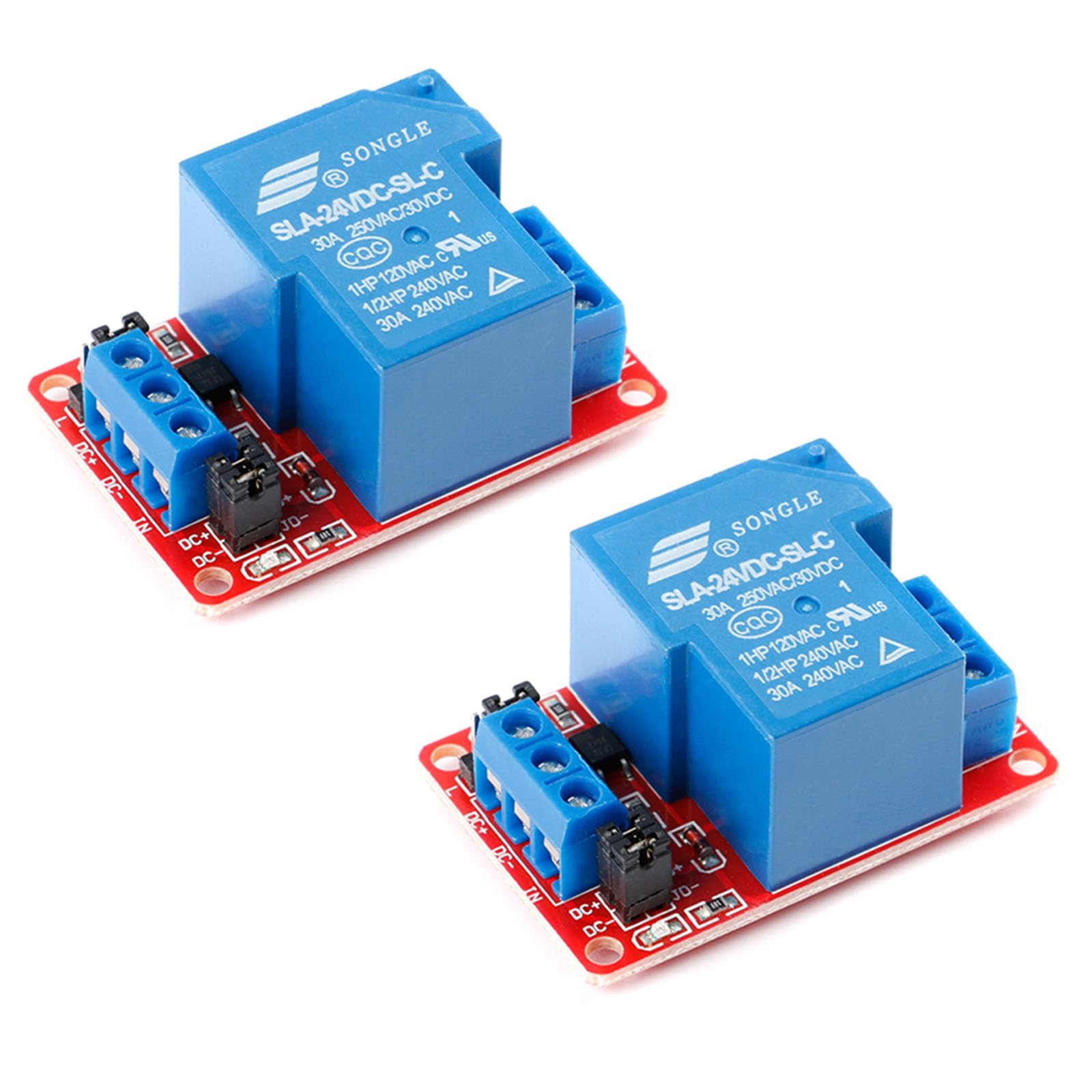
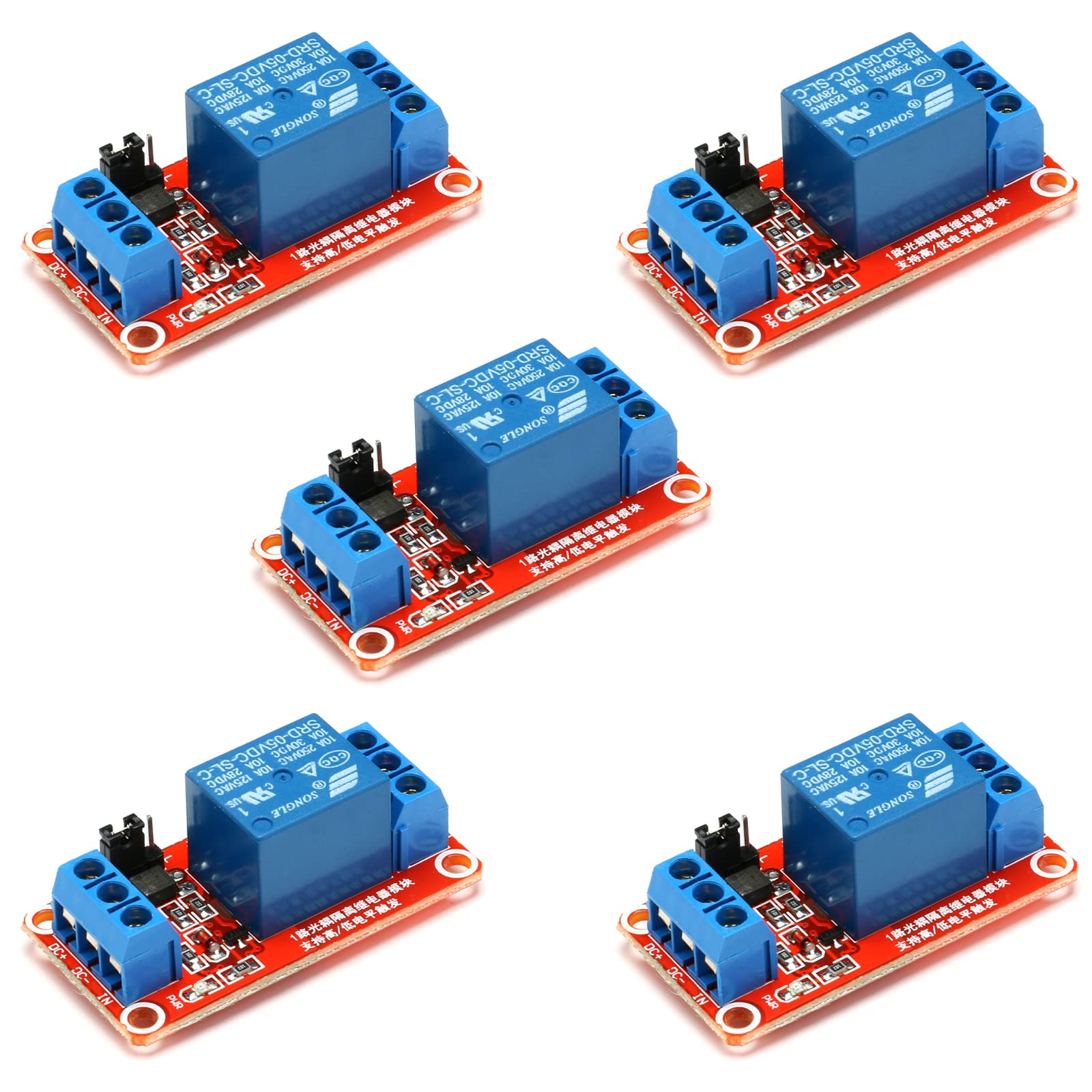
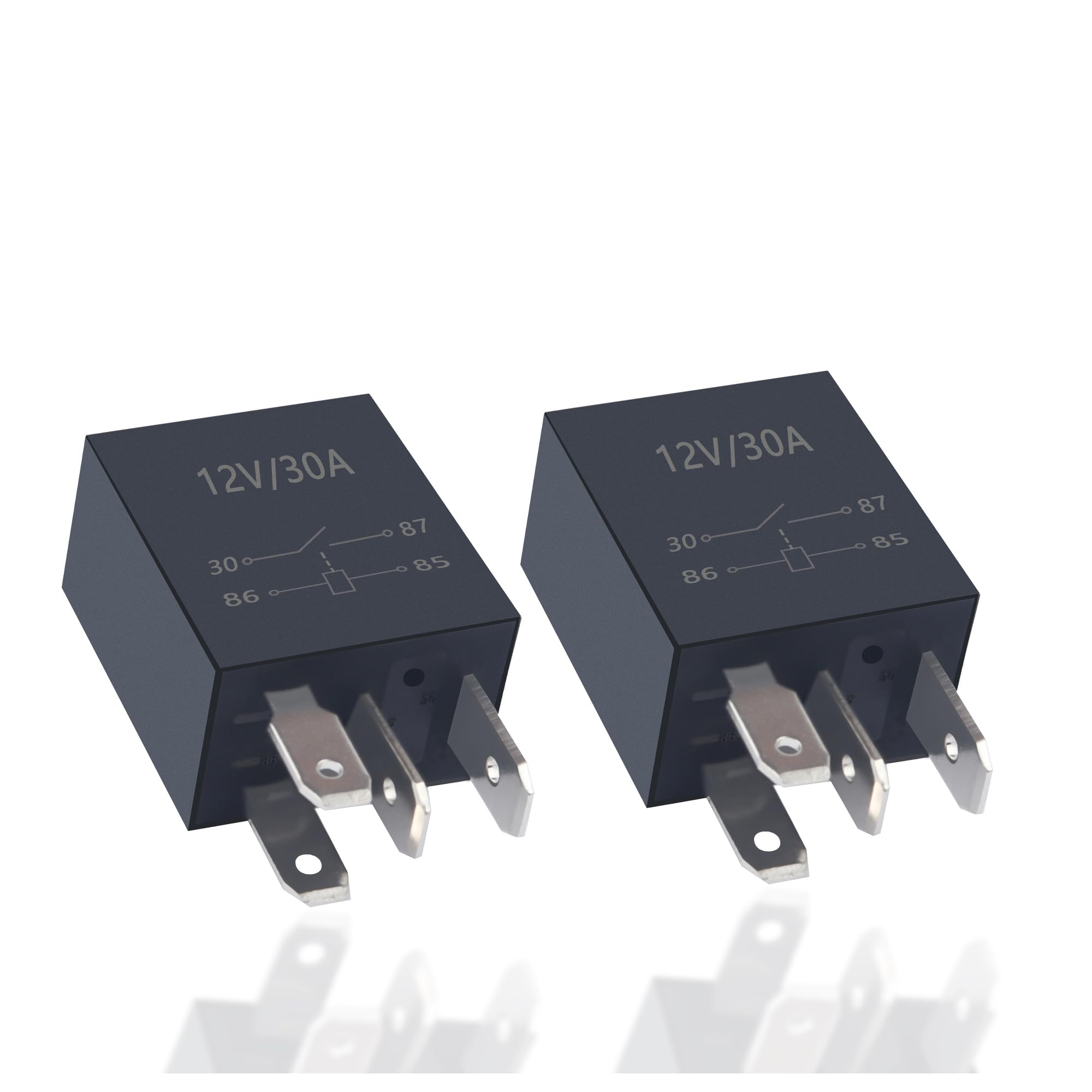
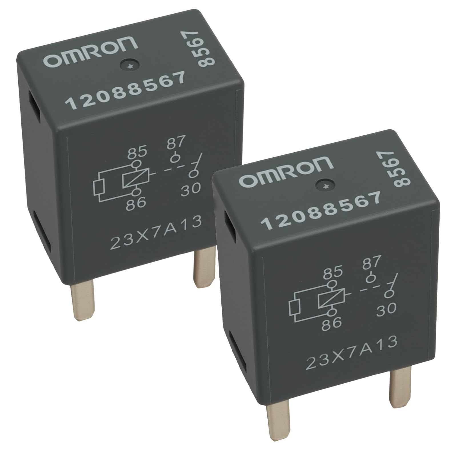
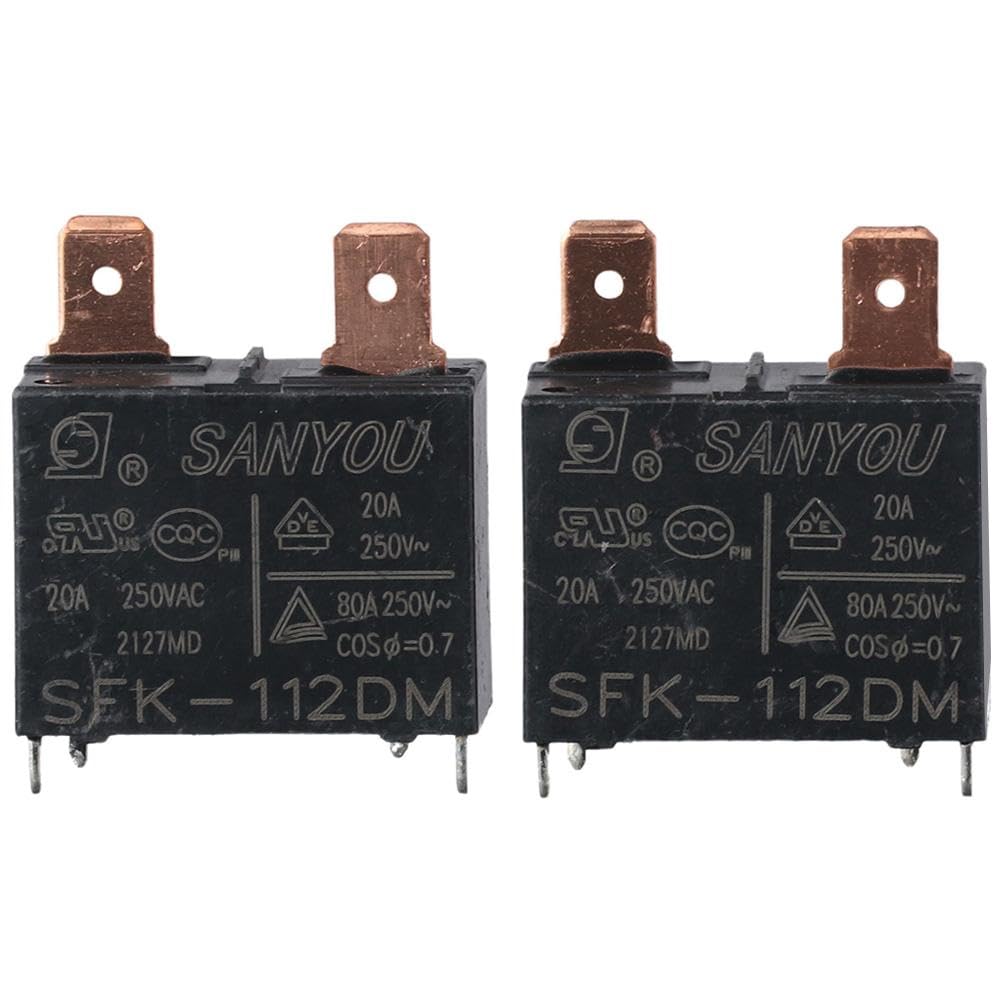
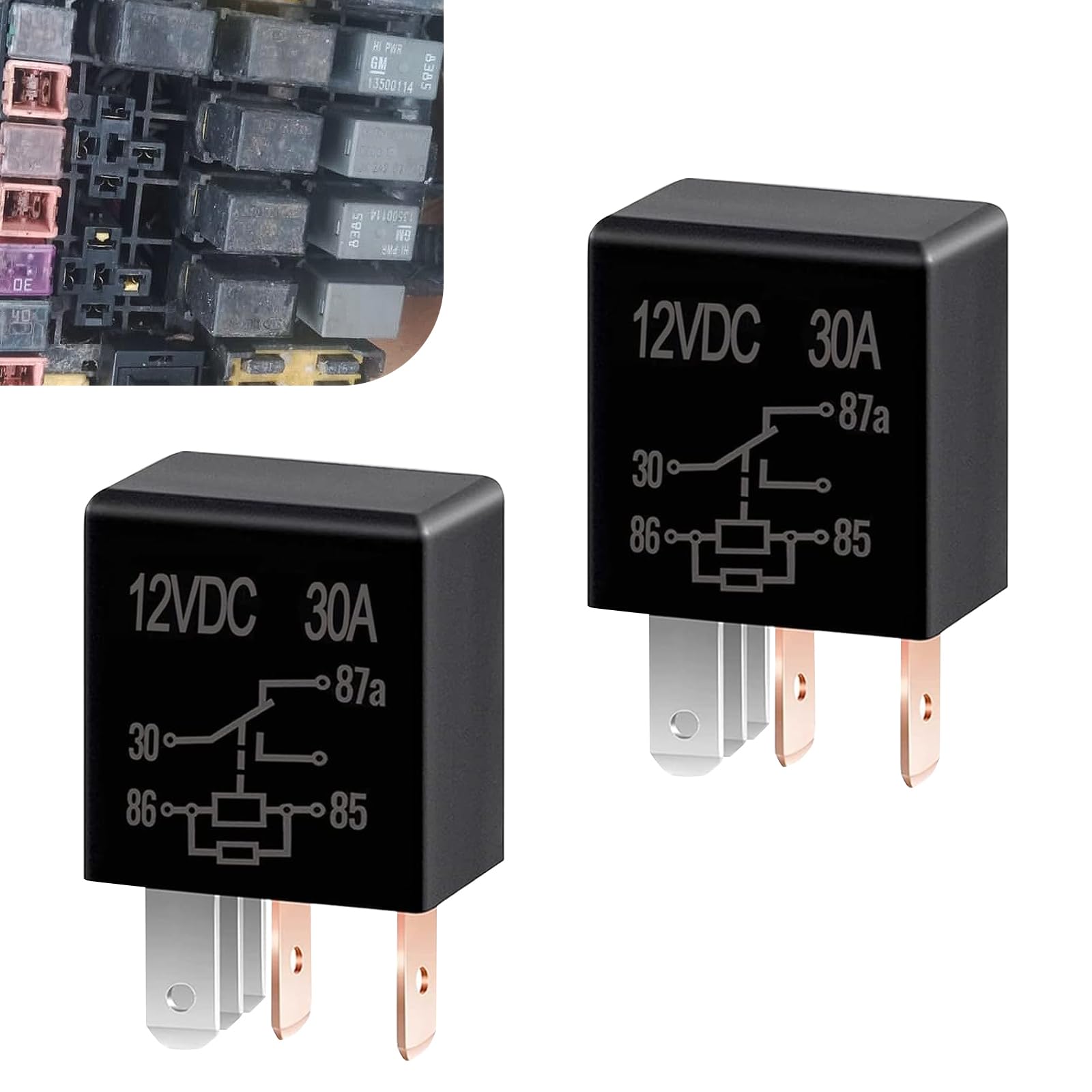
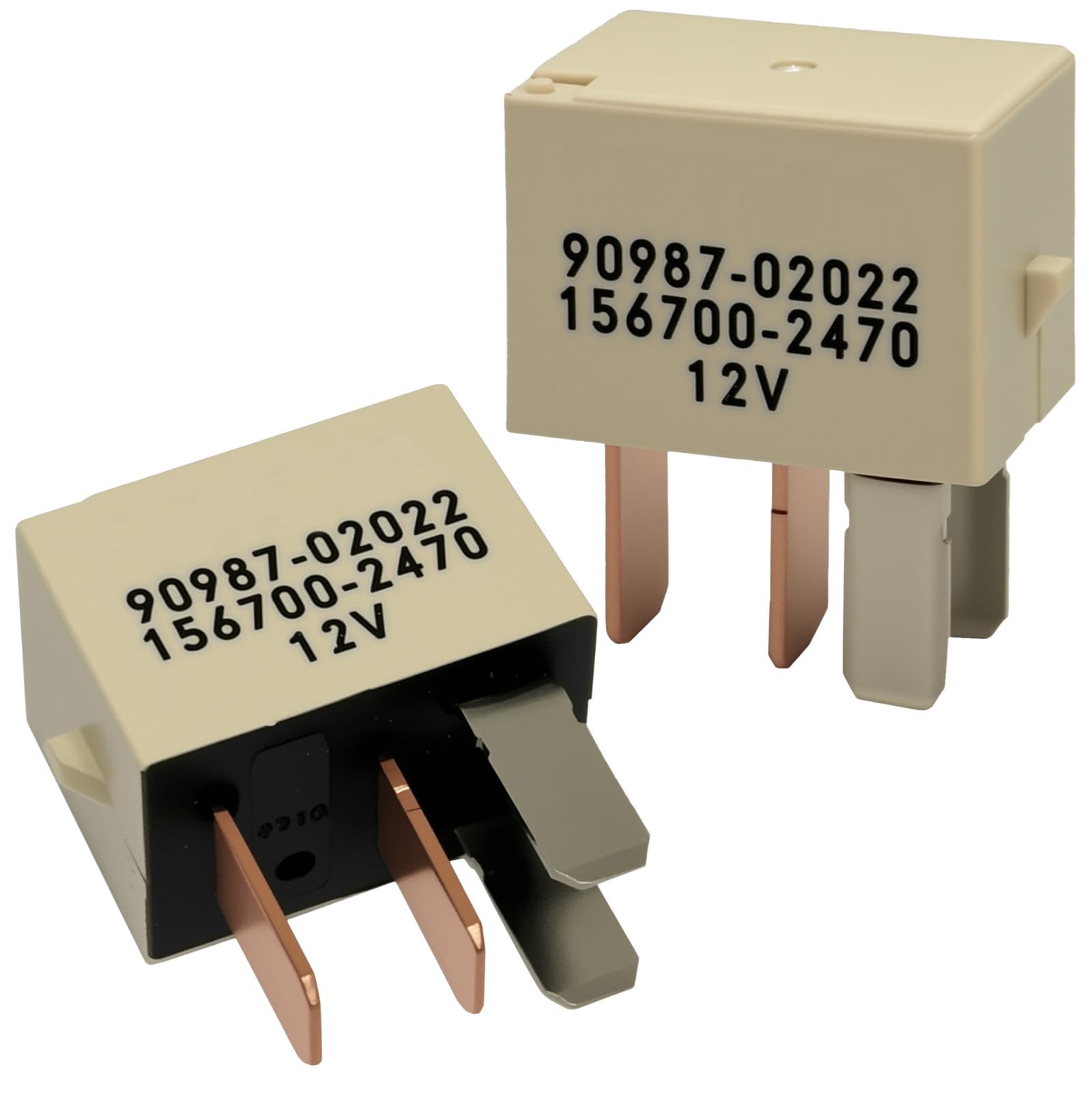
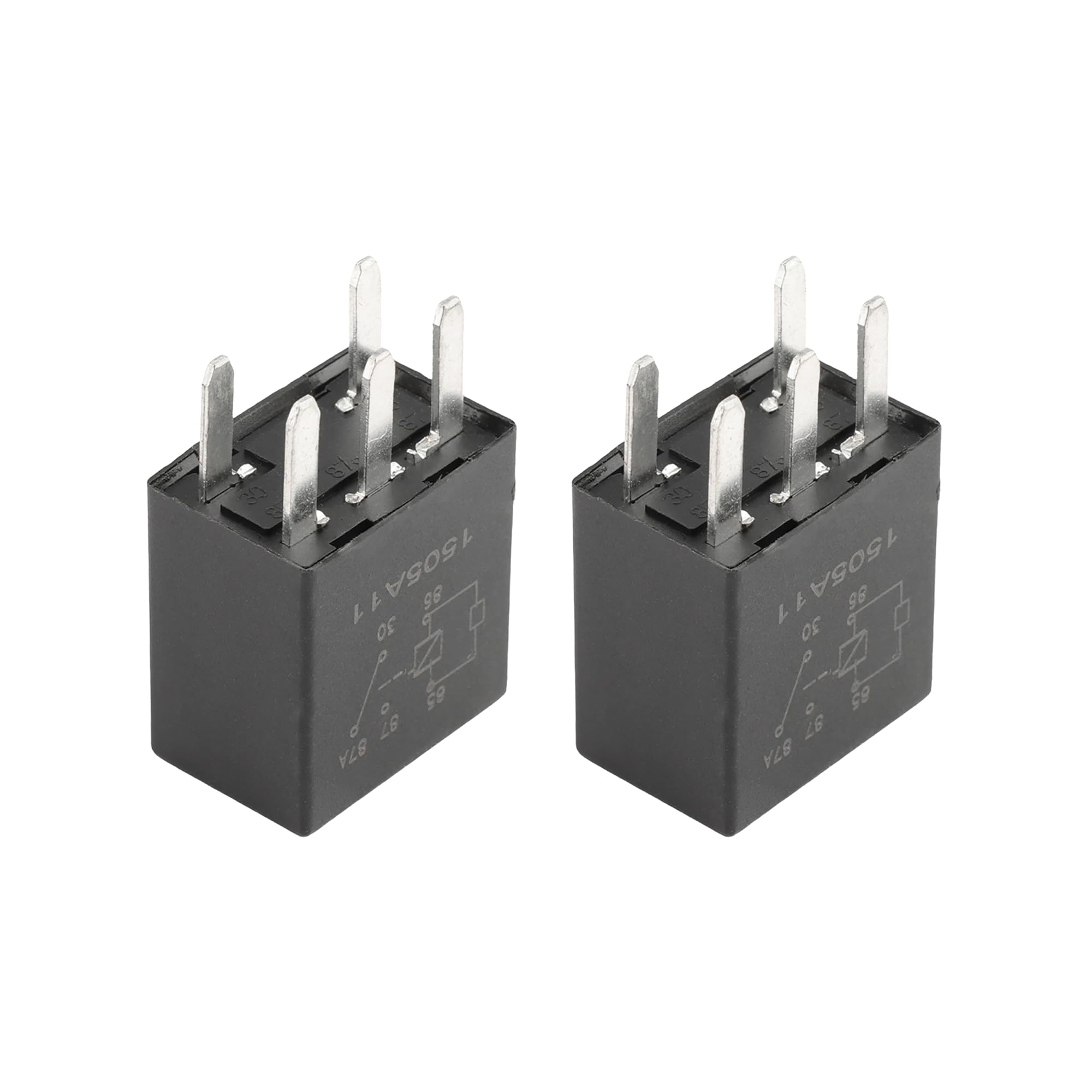
2Pcs 12V Relay Module 1-Channel 30A with Optocoupler Isolation Relay Module 5mA High and Low Level Trigger PCB
Disponibilidad:
En stock
En stock
Peso con empaque:
0.36 kg
0.36 kg
Devolución:
Sí
Sí
Condición
Nuevo
Nuevo
Producto de:
Amazon
Amazon
Sobre este producto
- Static current: 5mA; Maximum current: 80mA; Trigger current: 2-4mA
- Trigger voltage (low): 0-4V; Trigger voltage (high): 4.5-12V
- Module size: 50mm * 33mm * 24mm (length * width * height)
- There are 4 fixed bolt holes with a diameter of 3.1mm and a spacing of 44 5mm*27.5mm
- Double-sided PCB boards, with comprehensive layout considerations and stable performance
U$S 19,78
55% OFF
U$S 8,99
IMPORTÁ FACIL
Comprando este producto podrás descontar el IVA con tu número de RUT
U$S 19,78
55% OFF
U$S 8,99
Llega en 5 a 11 días hábiles
con envío
Este producto viaja
de USA ![]() a tus manos en
a tus manos en
![]()
Compra protegida
Disfruta de una experiencia de compra segura y confiable
![]() Garantía de entrega
Garantía de entrega
Con Tiendamia todas tus compras cuentan con Garantía de Entrega o devolución total de tu dinero.
Compras 100% seguras y garantizadas, para que pidas lo que soñás y lo recibas del mundo a tu puerta.
Saber más.
Tarjetas prepagas, debito, y credito
Paga hasta en 12 cuotas sin interés con tarjetas de crédito.
Visa
Mastercard
American Express
Dinners
Discover
Lider
Midinero
OCA
OCA Blue
Tarjeta PREX
Pagos a través de PayPal
Paga en dólares con Tarjetas internacionales a través de PayPal.
PayPal
Conoce más detalles
The 1-channel 12V relay module series uses patch optocouplers for isolation, with stable performance and user-friendly design. It can be triggered by high-level or low-level signals, and only requires 5mA current to drive a relay with a control capability of 30A. The module adopts power relays, small packaged optocouplers, high-power high-voltage transistors, red and green signal indicator lights, double-sided PCB boards, with comprehensive layout and stable performance. It is suitable for various single-chip microcontroller controls and can be widely used in various power control applications. 12V version Static current: 5mA Maximum current: 80mA Trigger current: 2-4mA Trigger voltage (low): 0-4V Trigger voltage (high): 4.5-12V Pin definition 1. DC+: Module DC power supply positive pole (trigger terminal voltage positive pole) 2. DC -: Module DC power supply negative pole (trigger terminal voltage negative pole) 3. IN: Signal trigger terminal (default trigger voltage is the same as the power supply) 4. JD+: Positive terminal voltage of relay control terminal 5. JD -: Negative terminal voltage of relay control terminal 6. Short circuit DC+and JD+with jumper caps, and short circuit DC - and JD - with jumper caps to trigger The voltage at the terminal is the same as that at the relay control terminal 7. Selection of high and low level triggering methods, as shown in the figure, when the jumper is connected to the L terminal, the IN terminal Triggered at a low level, triggered at a high level when connected to the H terminal 8. Normally closed end (NC): Relay normally closed end 9. Common Terminal (COM): Relay Common Terminal 10. Constant start (NO): Relay constant start